
Rotor-EZ Troubleshooting Information
 Rotor-EZ Trouble Shooting
SERIAL CONTROL (HyGain DCU-1)
Verify FLOW CONTROL IS NONE (H/W flow will cause it to fail)
For 9-pin connector bug from where cable plugs into computer pin 2 to PCB pad “T”
For 9-pin connector bug from where cable plugs into computer pin 3 to PCB pad “U”
For 9-pin connector bug from where cable plugs into computer pin 5 to chassis:
Start terminal emulator set to: Baud Rate 4800, Data Bits 8, Parity None, Stop Bits 1, and Flow None
Verify voltage at pad “U” is -7.7vdc (This could easily very by %10)
Press the CAPS LOCK, all commands are uppercase
Hold uppercase ‘V’ key and verify voltage at pad “U” is -7.3vdc (This could easily very by %10, but the voltage should be significantly less than the prior step)
A failure here indicate a cable or PC problem.
Remove the processor U1. Using a small piece of wire short U1 pins 17 and 18. Startup the terminal emulator (select the correct serial port, disable terminal ECHO), type on the keyboard and verify that what is typed is echoed to the display. This “wrap back mode” verifies that the serial communication is good all the way to the processor. Remove the wire and replace U1.
NOTE pressing the ‘;’ should release to brake for 5 seconds
Verify voltage at U5-12 is 5.0vdc
Hold ‘;’ key and verify voltage at U5-12 is 4.9vdc
Verify U5-2 is 10 +/- 1.5 vdc
Verify U5-6 is -10 +/- 1.5 vdc
A failure here indicates a PCB problem.
Misc. Additional Commands
Send the command “AP1000<CR>”, verify rotor turns to North.
Send the command “AI1;”, verify the unit responds with “;000” +/- 3 degrees
CALIBRATION FAIL:
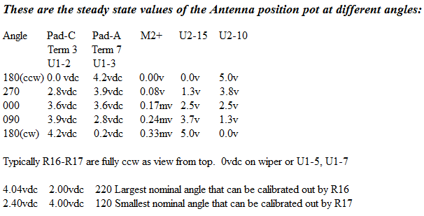
Verify that the meter will reach the full clockwise and counter clockwise deflections when the set pot is manipulated and R15 and the meter zero have been calibrated. If this fails, verify that U1-12 and U2-15 produce 0 to 5VDC as the set pot is manipulated, otherwise, verify that the resistance from U1-2 and U1-3 are approx 4.7k(+/- 500 ohms). If one of these nets has a short in it, the unit will appear to work correctly with the exception of not hitting the endpoints. Look for solder bridges in the nets that failed.
PRETEST FAIL:
Verify orientation of diodes, IC’s, capacitors. Verify IC U1 is seated properly in the socket.
Verify that +5vdc is across the two outer most terminals of the Set Pot. If this Pot is wired incorrectly fuse F1 will be blown.
EXCESSIVE NOISE:
Verify Antenna has a good earth ground.
Verify Pad “S” is tied to the chassis.
Verify Control box had a good earth ground.
These are the steady state values of the processor:
U1 pin 1 – 5vdc
U1 pin 2 – 5vdc (without rotor connected)
U1 pin 3 – 5vdc (without rotor connected)
U1 pin 4 – 5vdc
U1 pin 5 – 0vdc (dependent on R16)
U1 pin 6 – 0vdc
U1 pin 7 – 0vdc (dependent on R17)
U1 pin 8 – 0vdc
U1 pin 9 – 2vdc
U1 pin 10 – 2Mhz sine wave
U1 pin 11 – 0vdc
U1 pin 12 – 2.5vdc (pwm, 8ms sqr wave )
U1 pin 13 – 5vdc (pwm, 8ms inverted impulse)
U1 pin 14 – 0vdc
U1 pin 15 – 0vdc
U1 pin 16 – 0vdc
U1 pin 17 – 5vdc
U1 pin 18 – 5vdc
U1 pin 19 – 0vdc
U1 pin 20 – 5vdc
U1 pin 21 – 5vdc (depending on Config.)
U1 pin 22 – 5vdc (depending on Config.)
U1 pin 23 – 5vdc (depending on Config.)
U1 pin 24 – 5vdc (depending on Config.)
U1 pin 25 – 5vdc (depending on Config.)
U1 pin 26 – 5vdc (depending on Config.)
U1 pin 27 – 5vdc (depending on Config.)
U1 pin 28 – 5vdc (depending on Config.)
These are the steady state values of the analog switch:
U2 on the top-side of the device its self not the pads.
U2 pin 1 – 0vdc
U2 pin 2 – 5vdc
U2 pin 3 – 0vdc
U2 pin 4 – 5vdc (DON’T CARE)
U2 pin 5 – 5vdc
U2 pin 6 – 0vdc
U2 pin 7 – 0vdc
U2 pin 8 – 0vdc
U2 pin 9 – 0vdc
U2 pin 10 – 2.5vdc
U2 pin 11 – 5vdc
U2 pin 12 – 0vdc
U2 pin 13 – 5vdc
U2 pin 14 – 5vdc (pwm, 8ms inverted impulse)
U2 pin 15 – 2.5vdc (pwm, 8ms sqr wave )
U2 pin 16 – 5vdc
Contact Information:
sneitzer@ia.net


 Webmaster NØUN