
Serial Troubleshooting
How to Troubleshoot Serial Communications
So something happened, and now your RotorCard or Rotor-EZ isn’t responding to computer control? Or maybe you built a Rotor-EZ board from a kit, but serial communications don’t seem to work? This article will help you troubleshoot the problem.
This article should not be viewed as a complete guide to repairing the equipment. The advice in this article is only meant to suggest troubleshooting steps to take; the technician is solely responsible for his or her own safety, and the safety of the equipment.
Before taking things apart, you may wish to start with easy tests. Check to see if the serial port or USB adapter is configured correctly. The serial port or USB adapter should be set for 4800, 8, N, 1 (4800 bps, 8 data bits, no parity, and 1 stop bit) with neither hardware nor software handshaking. Some other software programs, such as the Palm Pilot HotSync software, are known to take control of all the serial ports on a computer, so make sure that no programs that might take control of the serial port are running.
Now might be a good time to see if software is the problem. One way to test the software is to try a different rotator control program. A more advanced way to test whether software is the problem, for expert troubleshooters only, is to communicate with the RotorCard or Rotor-EZ CPU directly using a terminal emulator program. When using a terminal emulator to talk to the CPU, know that the CPU does not echo keystrokes. The CPU waits for a valid command, and then acts upon it immediately. Invalid commands cause the CPU to “lock up”; the only way to recover is to switch the power off and on again. When using a terminal emulator to test serial communications, the best command to use is an upper-case “V”. (No <Enter> key is required to follow the “V”). Upon receiving that single character, the CPU should immediately return a version string similar to “ROTORCARD © IDIOM PRESS”. If the version string is received, then serial communications works.
If the problem does not seem to be software, then it is time to turn your attention to the hardware. Often the easiest way to find a hardware problem is by inspection. Unplug the control box from mains power and take the cover off. Inspect the RotorCard or Rotor-EZ, which will be called “the board” for the rest of this article. If you built the board from a kit, triple-check your soldering with a magnifying glass and a bright light; sometimes a cold solder joint will work for a short time, and then fail. Does the control box smell like burnt electronics? Are there any burnt components on the board? If everything looks okay, plug the control box back into mains power, turn the control box on, and check to see if the board is getting power. You must be very careful, because mains power is present in the control box. The safest way to measure the voltage is to use voltage probes with spring-loaded hooks, and connect the hooks before restoring power. If you have a Rotor-EZ, see if you can make the rotator turn by using the front panel controls. If you have a RotorCard, you should be able to measure +5 VDC compared to the control box ground at hole 8 on the left side of the RotorCard.
If the board looks okay and it gets power, then the next thing to do is to test the serial communications chain. When testing the serial communications chain, one must consider every device in the chain, including the serial port, the connectors, and the cable, as well as the RotorCard or Rotor-EZ.
The easiest way to test the serial port is to try using a different computer, or a different port on the same computer. If you are using a USB-to-serial adapter, try using a different adapter. For some reason, not every USB adapter works with every computer and every serial device.
If the serial port works, then the next step is to test the cables, connectors, and board wiring with a loopback test. The loopback test requires a software program called a serial communications terminal emulator. Windows XP and earlier versions of Windows include a terminal emulator called HyperTerminal; if it’s not already installed on your computer under “Start > All Programs > Accessories > Communications”, then you may need to install it from the Windows CD.
If you are running a later version of Windows, or a different operating system, then you will need to find a different terminal emulator. For Windows, Tera Term 4.71 has been successfully tested on Windows 7. It’s free and open-source software. If you find a different program you like, send an email to contact@hamsupply.com and we’ll mention it here.
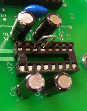
Picture showing MAX232 socket with pins 13 and 14 bridged
Unplug the control box from mains power; the loopback test does not require that the board have power. Carefully remove the MAX232 integrated circuit from its socket; the MAX232 is sensitive to electrostatic discharge, so take the appropriate precautions. Bridge pins 13 and 14 of the MAX232 socket with a component lead or other piece of thin solid wire, as shown in the following picture:
Next plug the serial cable into the serial port on your computer, and run HyperTerminal or another equivalent serial communications terminal program. If the test is successful then you should be able to type text and have the text echo to the screen, just as if you were typing text into a word processing program. If the test fails, then no text should appear on the screen as you type.
The loopback test is very simple, really. All you are doing is connecting the RS-232 port TX pin to the RX pin. The signal path includes the serial cable, wire traces on the board, the socket, and your temporary bridge. If the test is successful then you know that the serial port is good, and that signals are getting as far as the MAX232 socket. If the test fails then there is a problem with the serial port, the socket, or somewhere in between.
If the loopback test failed, you can use a multimeter to test for continuity between the serial cable connector and the MAX232 socket. Typical multimeter probes are too fat to make a good connection with the holes in the RS-232 cable connector; I attach the probes to clipped component leads, and poke the leads into the holes in the RS-232 cable connector and the socket. There should be continuity from pin 2 of the RS-232 plug to socket pin 14, from RS-232 pin 3 to socket pin 13, and from RS-232 pin 5 to ground on the board (on the RotorCard the ground is connected to hole 5 on the left edge of the board).
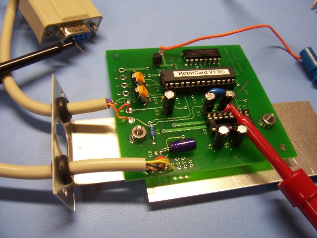
Testing for continuity between the RS-232 cable plug and the MAX232 socket
If the loopback test succeeds, but the board still doesn’t work, then it is time to try swapping components on the board. The MAX232 seems to be the component that fails most often when the board is hit by an electrostatic discharge such as a nearby lightning strike. MAX232IN ICs are commonly available from electronic parts suppliers, and are also available from Idiom Press. Rotor-EZ and RotorCard CPUs are available only from Ham Supply/Idiom Press or our partners.
Most of the time, serial communications failures turn out to be simple electrical continuity problems, like a broken wire or a bad part. However serial communications requires more than just continuity, and sometimes another problem is at fault. Some more obscure serial communications problems include RF getting into the line, other electrical noise on the line, timing issues, and so on. If you haven’t been able to locate the problem yet, then it may be necessary to swap additional components on the board, such as the electrolytic capacitors connected to the MAX232 chip, or the three-pin resonator that provides a timing signal to the CPU. Viewing the serial signals on an oscilloscope may also help.
If you are really stuck and you can’t find the problem, then it may help to bring in another technician. Many times I have found that just summarizing the problem for another technician, and explaining what steps have been taken so far, helps me to think of new troubleshooting ideas. Another person might think of steps to try that you may have missed, or he or she might see something that you didn’t.
Good luck with your troubleshooting!


 Webmaster NØUN